Installing the GM VKE 1000 Keyless Entry System — 1984–1989 C4 Corvette
1984–1989 C4 Corvette · Recovered DIY Guide
by Bryan A. Thompson — last revised July 12, 2001
About this restoration: The original guide at
batee.com/corvette/keylessentry/is no longer online. This page was reassembled on August 12, 2026 from Internet Archive (Wayback Machine) captures spanning 2003–2017, with the wiring chart, schematics, and factory manual scans that were originally separate links merged inline. The text is unchanged from the February 2006 capture.Four scan files were never archived and could not be found in any other web archive: factory install manual pages 8–11 and the user manual's cover and first spread. Everything else, including the complete wiring chart, was recovered — and the lost pages' content is reconstructed in Appendix C from the manual of the DEI 711T, the Directed Electronics unit the VKE 1000 was rebadged from.
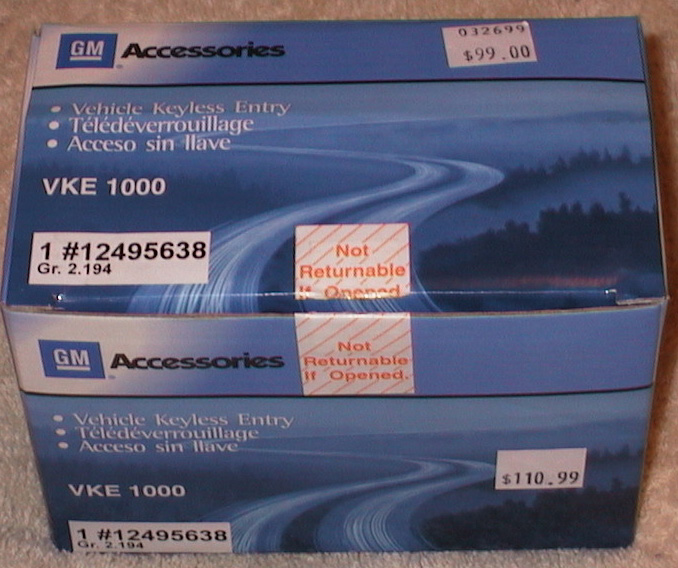
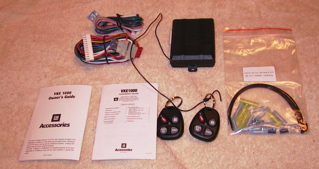
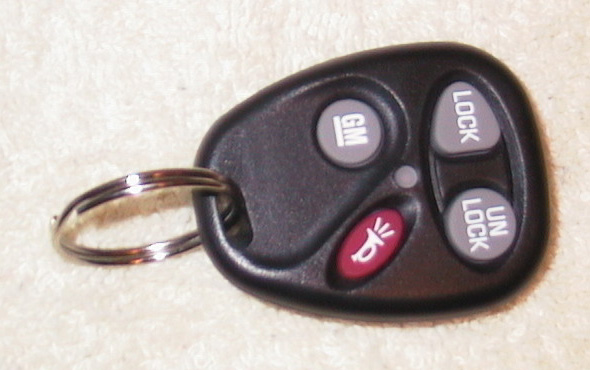
Note: These instructions apply to my 86 Early Corvette only. Wiring should be similar on 84–89 models, but use the Corvette Shop Manual for your year Vette to adapt these instructions for different model years. In particular, the 84s and some 85s used a different lock switch wiring circuit. Refer to your Corvette Factory Repair Manual for more info.
Note: This installation is compatible with the factory alarm.
What you'll need to install the VKE 1000
- VKE 1000 Kit ($99 at your GM dealer)
- 30A SPST Relay (to make the VKE 1000 compatible with the factory alarm) — $6
- 30A SPST Relay (to flash the parking lights when locking or unlocking) — $6
- Soldering Iron
- Electrical Solder (Rosin Core, large diameter)
- 12Ga Stranded speaker wire (25 ft)
- 3M Super77+ Electrical Tape — $3/roll
- 7mm socket
- 12" to 18" 1/4" extension
- 1/4" ratchet
-
2 Phillips Screwdriver
- Wire ties (5")
- 5/16" wrench
Optional
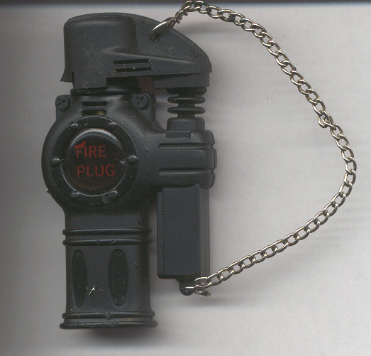
- Convenience store torch (for soldering large wires) — $5
- Corvette Shop Manual — $90–$120, worth every penny
- "Corvette" passenger side pad replacement kit — $49–$59
- "No Cut" wire strippers — $15
Tips
- Mount the receiver inside the car — the inside of the doors get really wet!
- Mount the receiver as high as possible — improves reception and remote range.
- Don't connect the black wire permanently mounted to the receiver to anything — that's the antenna.
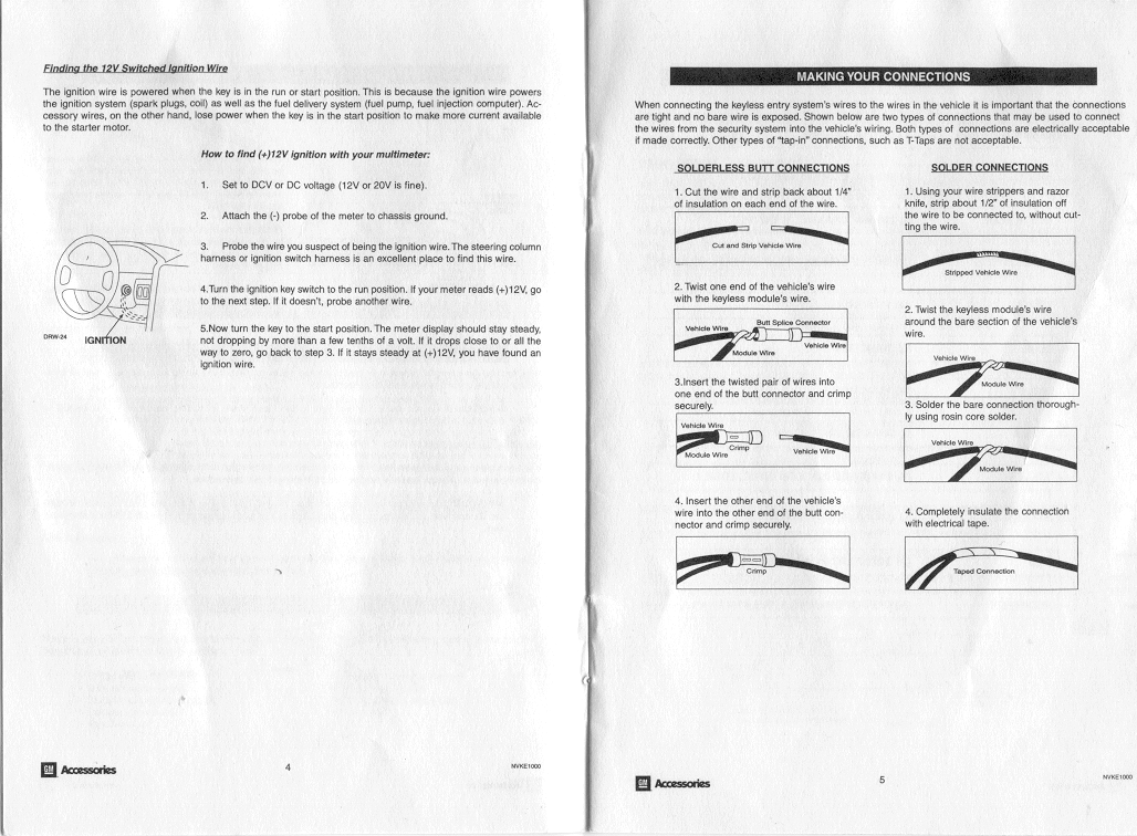
- Don't use the crimp connectors that come with the kit — solder and tape every joint.
- Those wires in the door are really big and take a lot of heat to solder. A $5 convenience-store torch works great.
Pre-Installation
Configure the VKE 1000
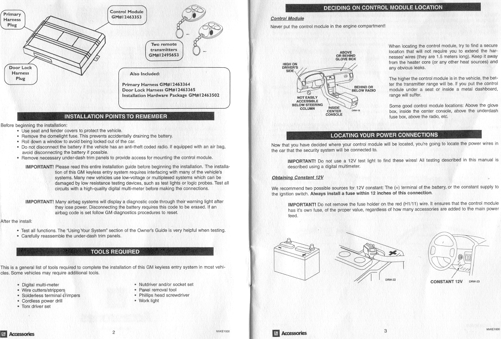
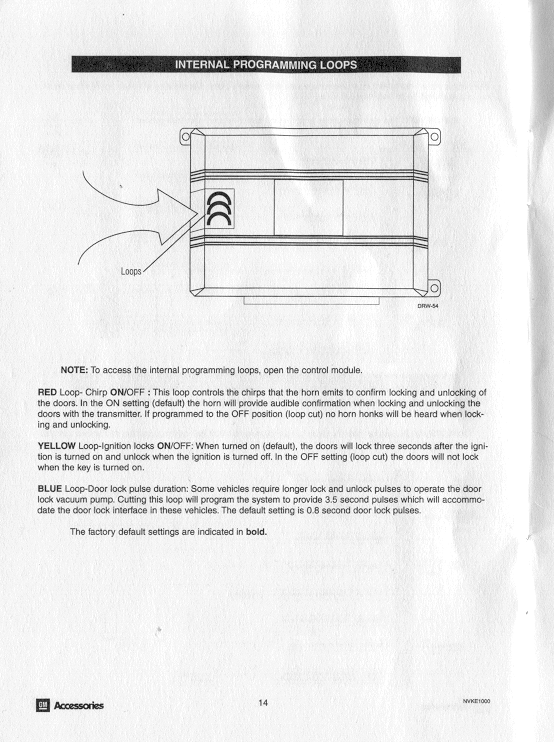
Check the three hardware options on the VKE 1000 module and set the switches/jumpers:
- a) Horn chirp on lock/unlock — annoying. Duration randomly ranges from 1–15 seconds. Can be silenced permanently or via button combo on the transmitter.
- b) Lock doors when ignition on, unlock on ignition off — cool but annoying if you crank twice.
- c) Lock pulse duration — no change necessary.
Installation
⚠ WARNING: REMOVE THE POSITIVE BATTERY CABLE!!!
Disassembly
Refer to your Corvette Shop Manual for details. Remove the trim around the digital cluster, then the center trim piece, then the dash pad, then the trim piece on the far RH side of the dash. Remove the passenger side hush panel and Corvette pad. Sit on the ground on the passenger side, look through the hole next to the fuse box, and using the 7mm socket, long extension and ratchet, remove the two screws holding the bottom of the pad. Then remove the two air ducts on the passenger side.
Wiring the VKE 1000
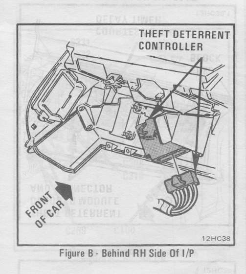
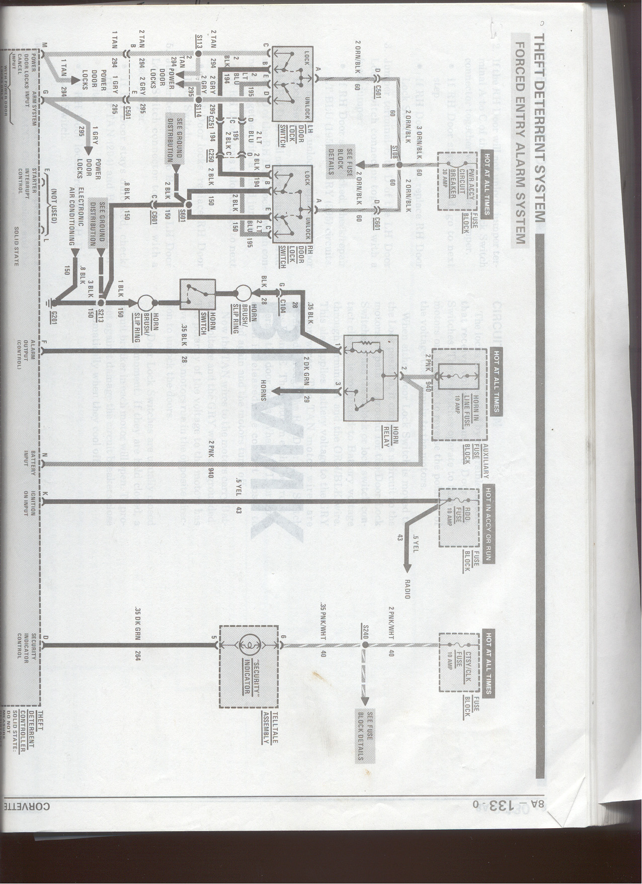
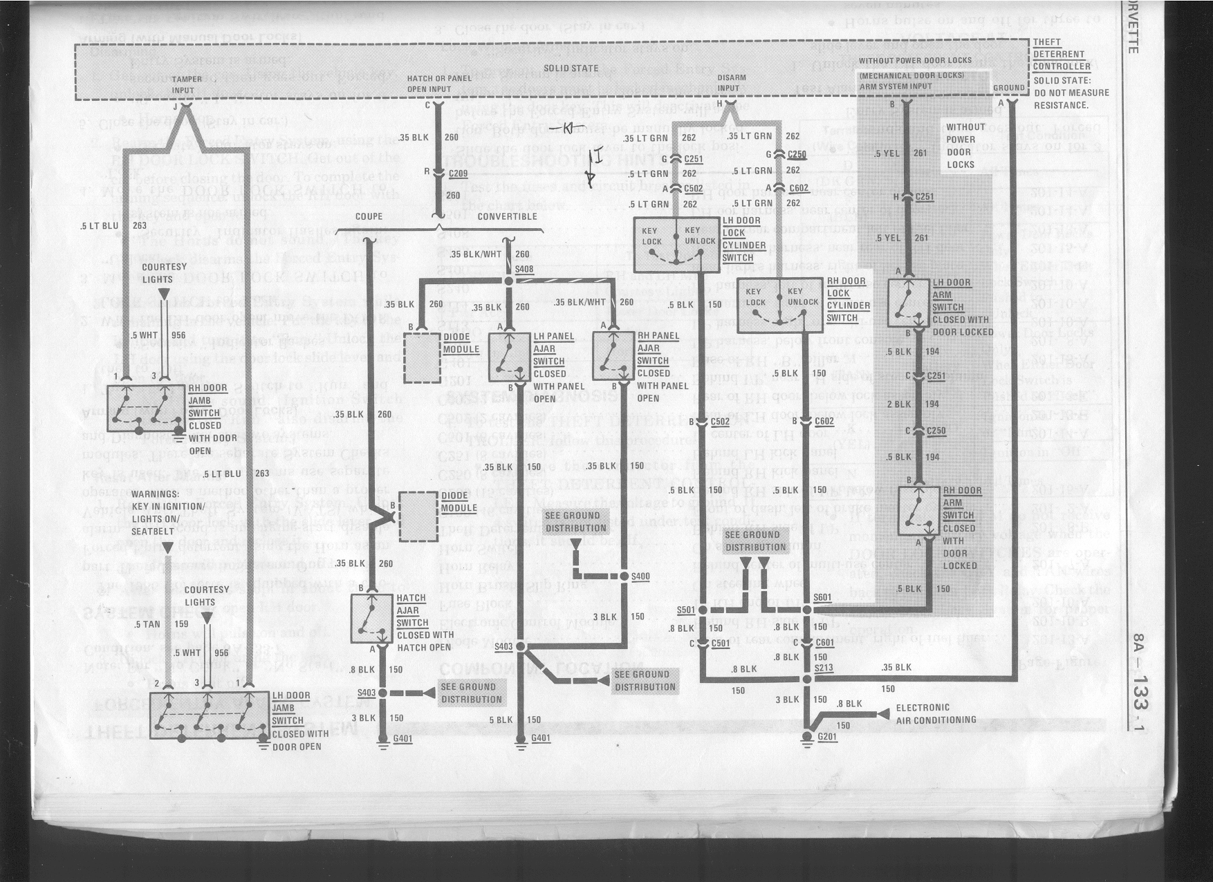
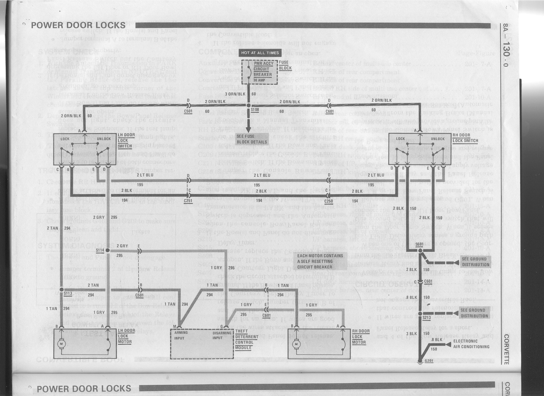
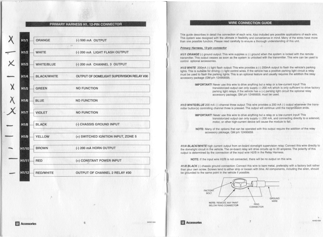
The Theft Deterrent Module is located on the passenger side of the dash. Using the wiring chart below, connect the appropriate portions of the wiring harnesses supplied with the VKE 1000 kit. Use a lot of electrical tape on the pink wire.
| Pin | Wire color | What it does | Where to connect this wire |
|---|---|---|---|
| H1/1 | Orange | Disarm TDM | Wire H (Lt Green) on Theft Deterrent Module (TDM) |
| H1/2 | White | Parking Light Flash | Coil wire for parking supervisor relay |
| H1/3 | White/Blue | Not Connected | Use this for controlling accessories |
| H1/4 | Black/White | Turn on Interior Light | Wire J (Lt Blu) on TDM |
| H1/5 | Green | No Function | No Connection |
| H1/6 | Blue | No Function | No Connection |
| H1/7 | Violet | No Function | No Connection |
| H1/8 | Black | Chassis Ground | Wire A (Black) on TDM |
| H1/9 | Yellow | Switched Ignition wire | Wire K (Yellow) on TDM |
| H1/10 | Brown | Horn Output | Wire F (Black) on TDM |
| H1/11 | Red | +12V Constant | Wire N (Pink) on TDM |
| H1/12 | Red/White | Open Hatch | Connect to one side of button in center console |
| Pin | Wire color | What it does | Where to connect this wire |
|---|---|---|---|
| H2/A | Red/White | Open Hatch | Connect to other side of center console button |
| H2/B | Black/White | Turn on Interior light | Wire A (Black) on TDM |
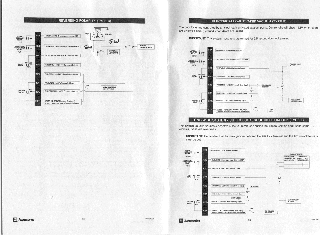
| H2/C | White/Black | Locks car | Black wire to pass side lock switch |
| H2/D | Green/Black | Locks Car | Black wire to wiring harness |
| H2/E | Violet/Black | 12V Constant Power | Wire N (Pink) on TDM |
| H2/F | Brown/Black | Unlocks Car | Lt Blu wire to pass side lock switch |
| H2/G | Blue/Black | Unlocks Car | Lt Blu wire to wiring harness |
| H2/H | Violet | 12V Constant Power | Wire N (Pink) on TDM |
| Terminal | What it does | Where to connect this wire |
|---|---|---|
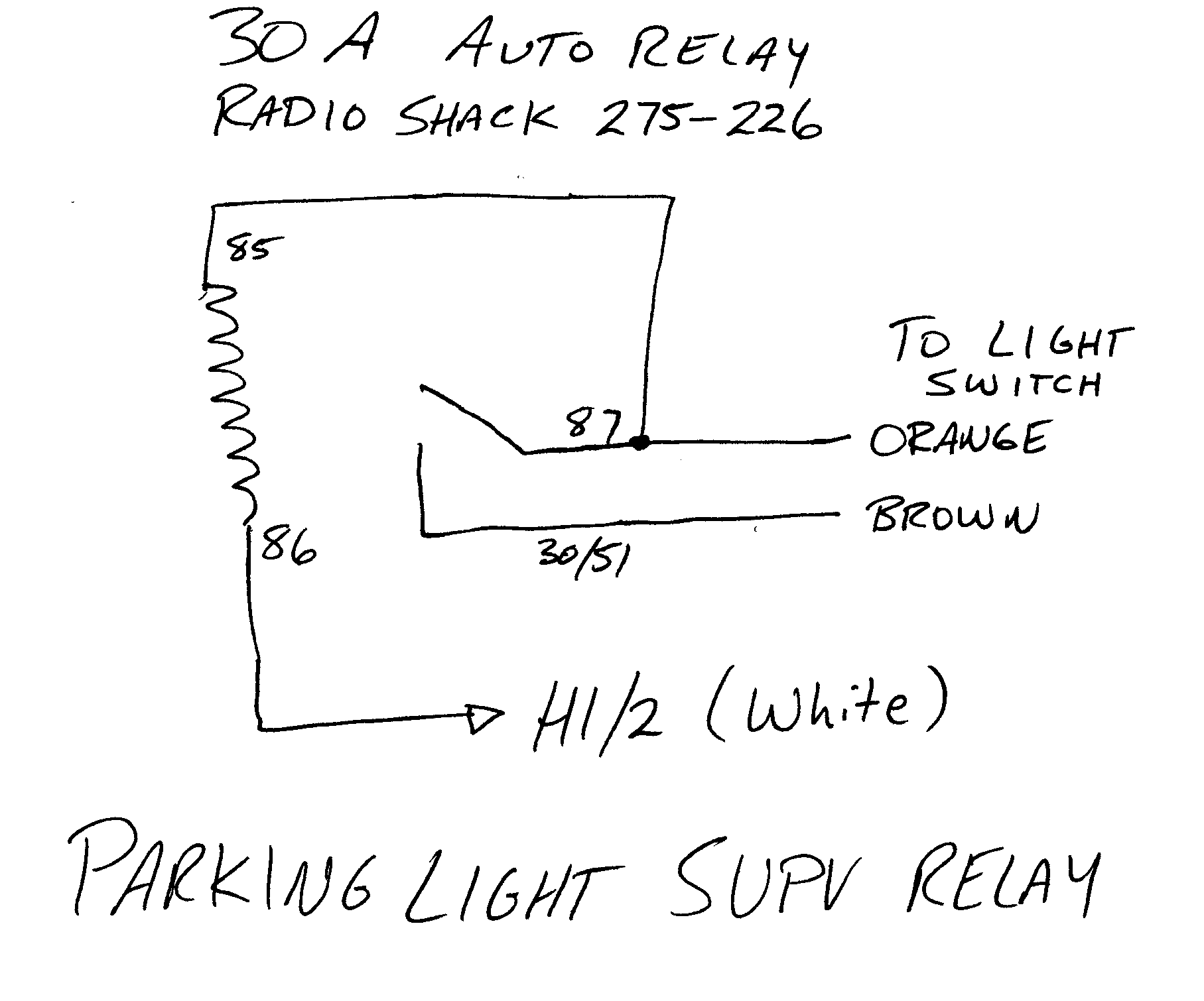
| 85 | Relay coil | Terminal 87 on Parking Supervisor Relay |
| 86 | Relay coil | Wire H1/2 on the VKE 1000 / terminal 87 on Prkng Light Relay |
| 87 | Flash parking lights | Orange Wire on the Headlight Switch |
| 30/51 | Flash Parking Lights | Brown Wire on the Headlight Switch |
| Terminal | What it does | Where to connect this wire |
|---|---|---|
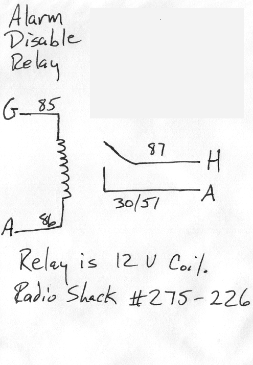
| 85 | Relay Coil | Wire G (Gray) on TDM |
| 86 | Relay Coil → Chassis Gnd | Wire A (Black) on TDM |
| 87 | Disarm factory alarm | Wire H (Lt Green) on TDM |
| 30/51 | Chassis Ground | Wire A (Black) on TDM |
Important: Remove the passenger side door panel. Locate the wires leading from the door lock switch. Follow these until they pass through a transparent connector (C250). Cut the Light Blue and Black wires and extend each of the four ends by soldering a 6 ft length of wire. Wrap connections with electrical tape (at least 4 times). Pass the extended wires through the wiring duct in the door with a coat hanger. Connect to the wiring harness as shown in the wiring chart.
Factory Alarm Disable Relay
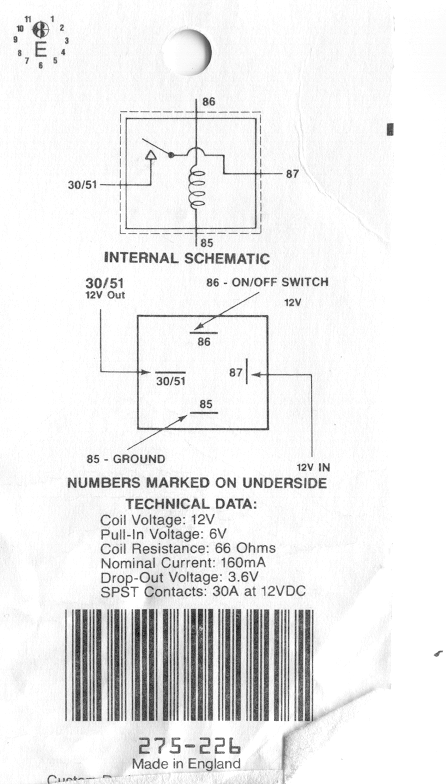
If you have the factory alarm, you'll need to wire a 30A SPST relay to disable it when the VKE 1000 activates the doors. Connect the relay coil between +12V (fused) and the VKE 1000's output. The relay contacts go in series with the alarm trigger wire.
Optional Installation: Parking Light Flash
Wire a second 30A SPST relay to flash the parking lights when locking or unlocking. Connect the relay coil to the VKE 1000 output and the contacts to the parking light circuit.
Testing
Before reassembly:
- Reconnect the battery
- Test lock/unlock with both remotes
- Test the trunk release
- Test the panic function
- Verify the factory alarm still works (if applicable)
- Check that the parking light flash works (if installed)
Reassembly
Reverse the disassembly steps. Secure all wiring with ties and tape. Reinstall all trim pieces.
Appendix A: VKE 1000 Factory Install Manual
Appendix B: VKE 1000 User Manual
Appendix C: DEI 711T Reconstructed Content
The DEI 711T is the Directed Electronics unit that the VKE 1000 was rebadged from. The following content was reconstructed from the 711T manual to fill gaps in the VKE 1000 documentation.
H2 relay harness (from the 711T guide)
H2/D green/white — input to the on-board alarm relay: supplies the voltage that appears on output H1/3. Feed it +12V (fused) for a positive output or chassis ground for a negative output.
H2/E green — input to the on-board trunk release relay: supplies the voltage that appears on output H1/12.
H2/A red/white — input to the on-board Channel 2 (trunk release) relay: supplies the voltage that appears on output H1/12. Feed it +12V (fused) for a positive output or chassis ground for a negative output.
H2/B black/white — input to the domelight supervision relay: sets the polarity of output H1/4 (ground for a negative door-pin circuit, fused +12V for a positive one).
H2/C–H2/H — power door locks: on-board relays interface directly with most factory lock systems drawing 30 amps or less.
Transmitter/receiver learn routine (from the 711T guide)
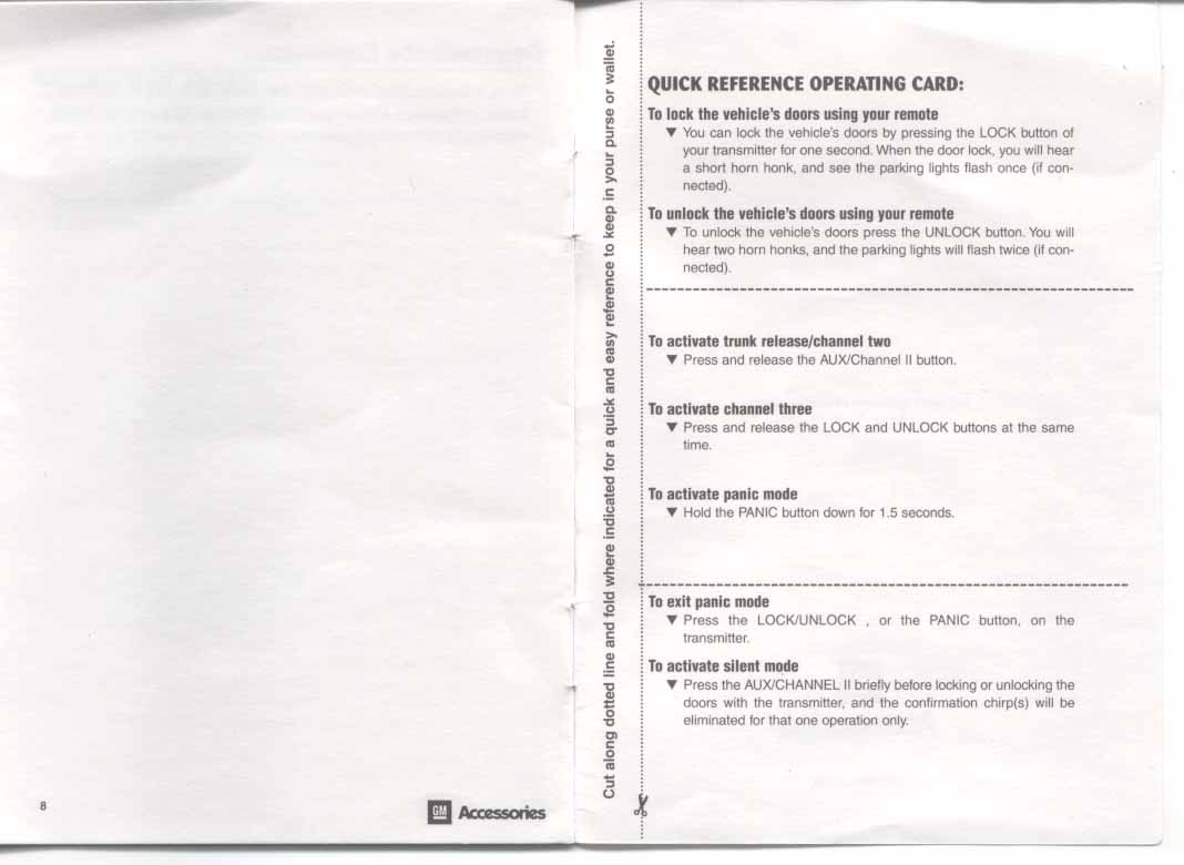
The system learns up to four transmitters. Factory programming: Button I is lock/unlock/panic, Button II is Channel 2 and silent mode, Buttons I+II together are Channel 3.
- Key. Turn the ignition to the run position (the yellow H1/9 wire must be connected).
- Valet/Program switch. Press and release the switch the number of times matching the channel to program (1 = lock/unlock/panic, 2 = Channel 2, 3 = Channel 3, … 9 = delete all transmitters and reset settings), then press once more and hold. The horn honks to indicate the selected channel.
- Transmit. While holding the switch, press the transmitter button that should control that channel. One honk confirms the code was learned.
- Release. The routine exits when the ignition is turned off, the switch is pressed too many times, or 15 seconds pass between steps — one long honk confirms exit.
Caveat: The 711T's routine uses a plug-in Valet/Program switch, which the VKE 1000 kit does not appear to include. The VKE 1000 module likely has the same 2-pin program port on the case, so a momentary-contact switch to ground may serve.
Source Files
Download the original PDF wiring diagrams:
Unless otherwise specified, the text and images are the copyrighted property of Bryan A. Thompson, 1996–2013. All Rights Reserved. Reassembled for personal reference from Internet Archive captures of batee.com/corvette/keylessentry/.